
Introduction
Have we really thought through what tomorrow’s machines might sound like when they hum? In a near-future workshop I picture, an electric motor sits at the heart of every device — quiet, precise, and smart — and data shows global motor-driven systems account for roughly half of industrial electricity use (a staggering figure, right?). I imagine fleets of drones, factories, and home appliances all running coordinated routines, each with an electric motor that learns a little more each cycle. The scene is speculative, yes, but the numbers push the question: how do we cut waste and increase lifespan without adding complexity? I ask this because I’ve stood beside engineers rewriting control loops late at night; they’ll tell you the same thing — small efficiency gains scale massively. So, where do we focus first — power electronics, control strategy, or materials? — and what trade-offs are we willing to accept? This piece moves from a comparative lens into practical choices, and then forward into what I believe will matter next.
Deeper Layer: Flaws in Traditional Brushless Solutions
To be precise: a brushless motor is more than a label — it’s a system of rotor, stator, sensors, and electronics. I start by breaking down how the typical brushless architecture operates: the inverter supplies timed PWM to phases, sensors feed rotor position to the controller, and field-oriented control (FOC) algorithms shape current to produce torque. That definition is simple but revealing — it also shows where things go wrong. First, many legacy systems use low-resolution hall sensors or open-loop commutation; the result is torque ripple and inefficient current draw. Second, power converters and inverters often run conservative switching patterns to protect components, which sacrifices efficiency. Third, control firmware is frequently treated as static code — debugged once and forgotten — so it can’t adapt to wear or changing load profiles. Look, it’s simpler than you think: small sensor errors multiply into heat and energy loss. I’ve watched teams chase mysterious vibration issues only to find a misaligned encoder or an outdated commutation table. We call that hardware-software mismatch. (And yes — funny how that works, right?)
Why does this matter to users?
Because hidden pains accumulate: increased maintenance, unpredictable failure modes, and inflated energy bills. For an appliance maker, the extra cost translates to warranty claims. For a robot integrator, the same fault means lost uptime. When systems lack adaptive control — say, a closed-loop FOC that learns inverter dead-time effects — small inefficiencies become big operational headaches. Terms you’ll see in field reports: inverter thermal throttling, torque ripple compensation, and CAN bus jitter. I don’t want to be alarmist; rather, I want us to aim at practical fixes: higher-resolution encoders, smarter PWM schemes, and periodic calibration routines. Those changes are not glamorous, but they pay off loudly in the long run.
Future Outlook: New Principles and Comparative Metrics
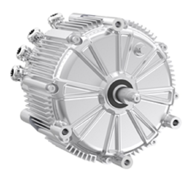
Now I shift forward. If Part 2 dissected the problems, here I compare emerging principles and show how they stack up. New technology principles center on three ideas: adaptive control, tighter integration of power electronics, and materials that reduce losses. For example, combining fast field-oriented control with predictive thermal models lets the inverter push closer to optimum without burning out. That’s where the pmsm motor fits into the picture — permanent magnet synchronous machines respond well to precise current shaping and benefit from higher-fidelity feedback loops. I want to be clear: this isn’t about shiny features. It’s about measurable gains — lower torque ripple, improved power factor, and extended bearing life. In practice, we test systems across load curves, and we often see 5–10% net energy improvement when adaptive control and smarter power converters are combined. — surprising to some, but repeatable.
What’s Next — real-world impact?
Let me give a short case-ish sketch. A packaging line retrofitted with higher-resolution encoders and updated vector control software cut its peak energy draw during acceleration by nearly 12%. Maintenance calls dropped, too. That outcome came from combining control strategy tweaks with decent hardware margins; nothing magical. I find that comparing options on three clear metrics helps teams choose wisely. Here are the 3 key evaluation metrics I recommend when selecting or upgrading motor systems: 1) System Efficiency Across the Duty Cycle (don’t just check idle points), 2) Adaptive Control Capability (can your controller learn and compensate?), and 3) Thermal Margin of Power Electronics (inverter and power converters rated beyond peak continuous load). Use those, and you’ll separate marketing claims from real gains. Also — small note — always test on realistic cycles; lab numbers lie in neat curves, but factories are messy.
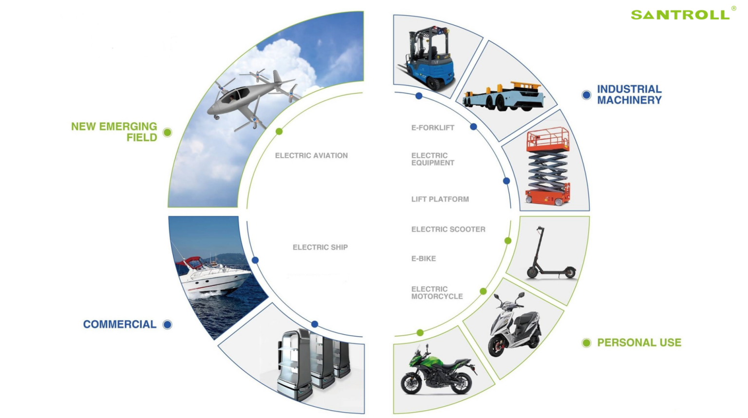
In closing, I’ve tried to keep this practical: we compare architectures, call out hidden pains, and point to measurable upgrades. My view is straightforward: incremental fixes with good measurement beat flashy redesigns that ignore system integration. If you want a partner who understands both the motor and the firmware, check out Santroll. I’ll keep tinkering, and I suspect you will too — the future hums quietly, waiting for better choices.