
Opening: why a framework matters
Organising a project to integrate a bespoke LiFePO4 battery enclosure into an operational supervisory control and data acquisition (SCADA) environment demands methodical thinking rather than improvisation. This framework-led piece outlines pragmatic steps so facilities managers and integrators can align electrical, communications and market-facing controls without disrupting service. If you are modernising a microgrid or retrofitting a residential site, consider this in the same breath as a home energy storage system procurement — the integration choices you make at the outset determine how gracefully a unit participates in demand response and grid services.

Stage 1 — assess the electrical and operational baseline
Begin with a clear inventory: site single-line diagrams, inverter and charger ratings, existing protection schemes, and the host SCADA tags. Confirm the battery management system (BMS) voltage, nominal capacity and state-of-charge (SOC) reporting capabilities; these affect both protection coordination and the unit’s ability to follow dispatch signals. Also verify circuit breaker settings and earthing arrangements so the LiFePO4 pack behaves harmoniously with protective relays. A detailed baseline reduces surprises during commissioning and is the true short-cut to a faster, compliant integration.
Stage 2 — design the physical and safety interfaces
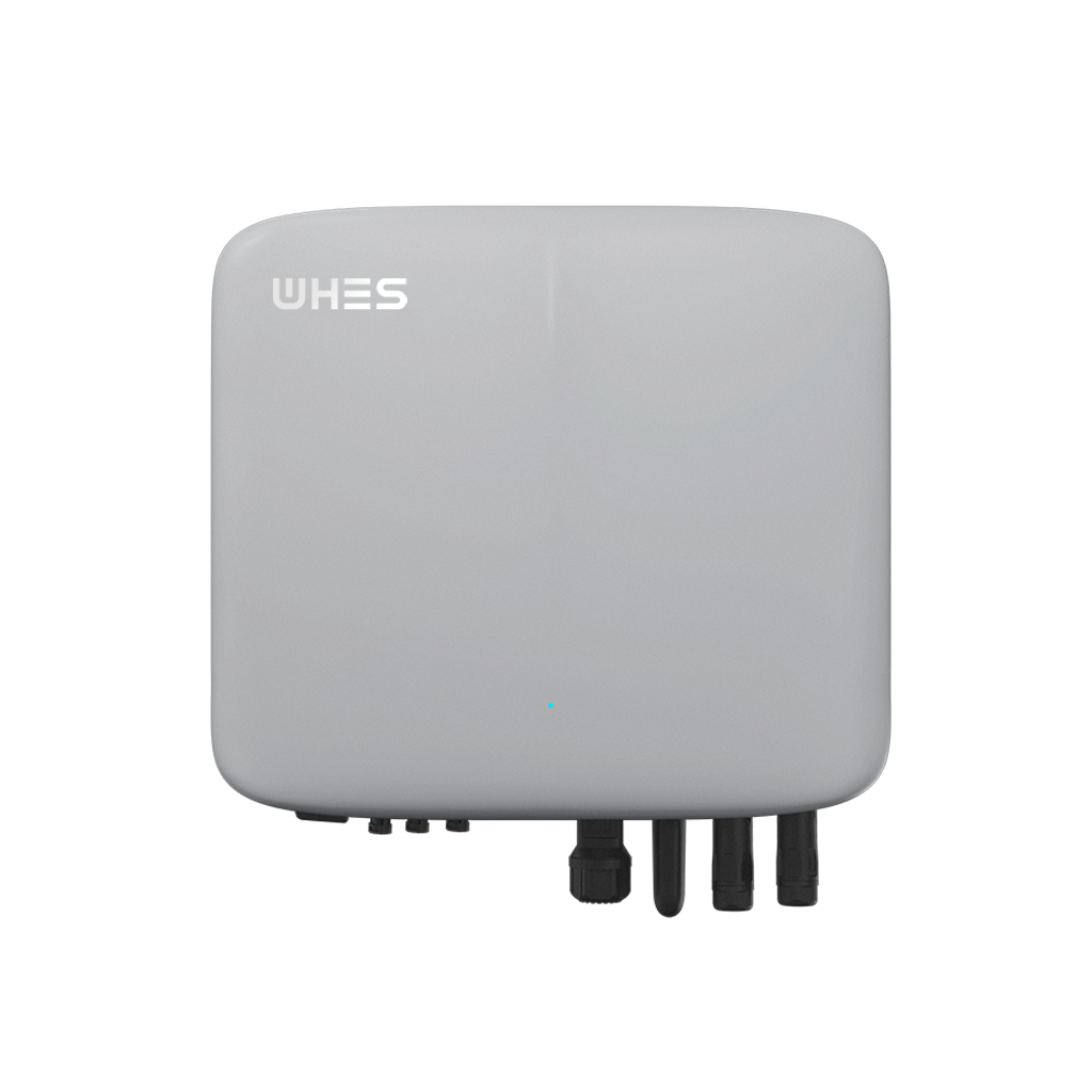
Mechanical fitment and thermal management must be decided alongside electrical wiring. Custom enclosures should meet ingress protection (IP) ratings appropriate to the location and leave service clearances for routine maintenance. Ensure ventilation or forced cooling is sized for continuous discharge scenarios, and that the enclosure accommodates fire mitigation measures where local codes mandate them. During one rooftop retrofit in southern California — when Public Safety Power Shutoffs were routine — installers prioritised rapid access to DC isolators to expedite emergency shut-downs; such small design choices matter in practice.
Stage 3 — align communications and control protocols
Communications determine whether the battery is merely present, or actively useful to grid operations. Confirm which protocol the SCADA master supports: Modbus RTU/TCP, DNP3, IEC 61850 or, increasingly, MQTT for cloud-native telemetry. Map the BMS and inverter registers to SCADA tags and demand response signals so you can expose dispatchable capacity, real-time SOC and alarm states. Where a gateway is required, choose one that preserves timestamps and uses redundant paths if the application is critical. Integrating telemetry correctly avoids phantom availability reports and ensures the battery participates reliably in demand response events.
Stage 4 — validate control logic with staged testing
Testing should be progressive: factory acceptance tests (FAT), site acceptance tests (SAT) and finally soft commissioning under controlled load. Begin with passive telemetry checks, proceed to local charge/discharge commands and only then permit remote dispatch from the SCADA operator. Simulate typical demand response events to confirm response time and state-of-charge constraints. Log all results against an acceptance checklist so contractual sign-offs are unambiguous — this is the difference between a functioning installation and one that needs repeat visits.
Common pitfalls and practical mitigations
Integrators frequently underestimate three issues: protocol mismatch, erroneous scaling of telemetry values, and insufficient alarm semantics. Protocol mismatch is avoidable with an early comms audit; scaling errors (voltage reported in millivolts, for instance) are pernicious yet trivial to catch in simulation. Alarm semantics matter because a generic “fault” tag is of little use during a DR event — you need precise states such as BMS cell imbalance, high-temperature warning or communications loss. A concise mitigation: insist on a signed mapping document from vendor registers to SCADA points and run an offline simulation with your SCADA historian.
There is also a human angle — technicians prefer clear labelling and simple recovery steps when an alarm trips in the small hours. Make life easier for them and the system will be more reliable.
Interoperability with demand response markets and aggregators
When the battery must participate in market-driven demand response, the integration expands to include market signals, telemetry cadence and verification logic. Confirm how your aggregator expects availability to be reported and how bids are validated; some programmes require 5‑ or 15‑minute energy telemetry, others expect day-ahead nominations. Where local islands or microgrids are present, ensure that islanding detection logic (and re-synchronisation procedures) is compatible with your inverter and SCADA controls. If you are implementing smaller residential clusters, treat them as distributed assets similar to other home battery backup systems — aggregation means standardised reporting and predictable fault handling.
Commissioning checklist (concise)
• Confirm mechanical and IP ratings, and that DC isolators are accessible. • Verify BMS-to-inverter signalling and charge/discharge limits. • Map and validate SCADA tags and timestamps using simulated events. • Execute FAT → SAT → soft commissioning and archive results. • Establish operational runbooks for alarm triage and DR event execution.
Real-world anchor and lessons learned
Across several recent deployments in the western United States — notably projects staged during the 2020–2022 wildfire seasons — teams found that rapid, reliable telemetry and an enforceable energy ceiling were decisive in keeping assets available for grid support. In those examples, the systems that succeeded had tight comms mapping, automated failover and a clearly defined DR acceptance test. These practical lessons underline why a formal framework is not merely bureaucratic — it materially improves availability and value capture.
Advisory close — three golden rules for selection and integration
1) Define measurable interoperability: require a published register map and test vectors for every protocol the asset will speak. 2) Insist on staged, witnessed commissioning: no remote control without a signed SAT that confirms alarm semantics and response times. 3) Value total system availability: evaluate vendors and integrators by historical uptime and documented incident response procedures rather than headline capacity figures.
In short, a thoughtful framework converts a custom LiFePO4 box from a stand-alone component into a dependable grid participant — and that dependable participation is exactly the asset WHES consistently engineers for in field deployments. WHES. —